
25 July 2025
The goal of this study was to use Computational Fluid Dynamics (CFD) simulations to analyze the aerodynamic differences between three road cycling arm postures—not time trial—all of which could be used comfortably and without compromising UCI rules for road cycling. The first one featured the hands holding the handlebar on the drops, the second one had the hands on the hoods while the third one also had the hands on the hoods but narrowed the distance between the elbows, bringing them closer to the body.
Drag was reduced by 4% from the first position to the second and by 2.6% from the second to the third. The positive result, when decomposed into frontal area and Cd, was due mainly to the progressive reduction of the frontal area, while the Cd had a lesser influence. The important drag reduction shows how a simple change in arms position can determine significant improvements due to local and global aerodynamic consequences on the cyclist's body.
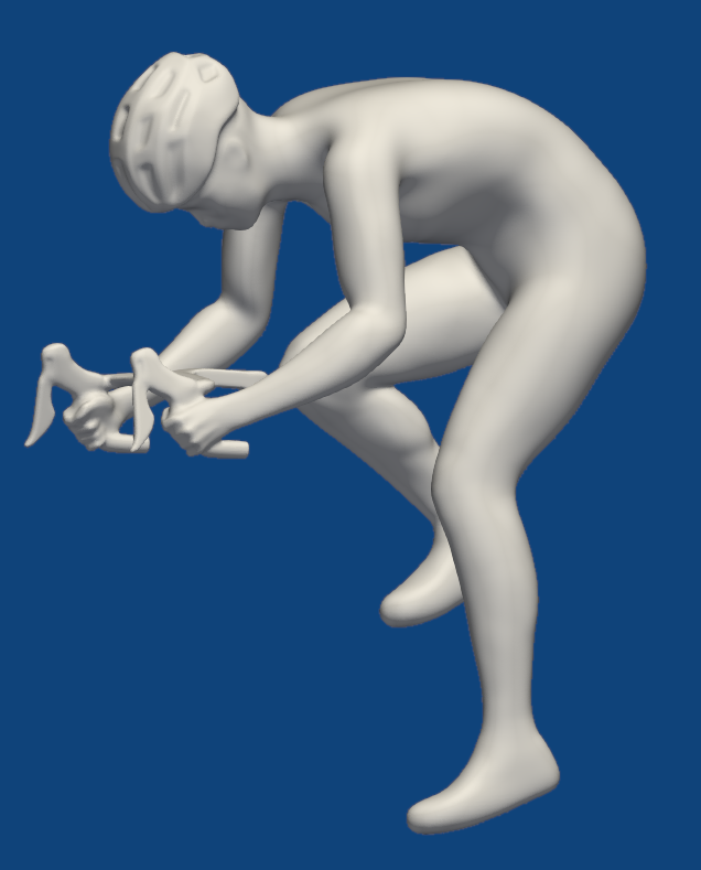
A competitive male road cyclist (26 years old, 1.73 m height, 62 kg weight) was selected for this study. The subject was chosen for his ability to maintain a highly aerodynamic posture, ensuring that changes in arm configuration would produce measurable differences in aerodynamic drag. The three positions were defined as follows:
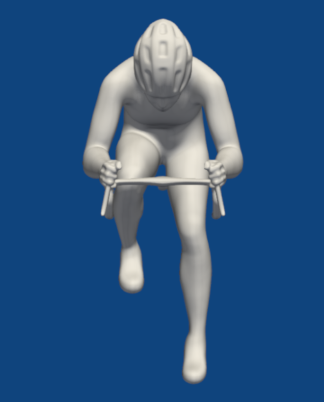
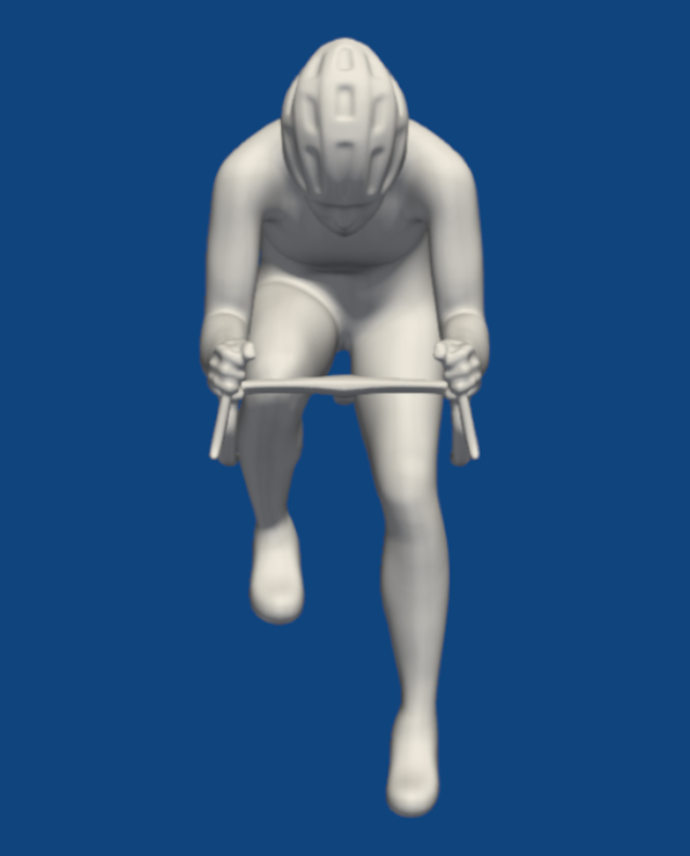
The posture of the rest of the body (head, trunk, and legs) was kept consistent across all three trials to isolate the aerodynamic effects of arm position. The trunk angle (measured as the angle between the line through the acromion and ASIS and the horizontal plane) was approximately 18°.
A 3D scan of the cyclist in a standing position provided the baseline geometry, which was then imported in Blender. A skeletal rig, composed of virtual bones and joints, was added to enable articulated movement of each body segment. Using still frames from a video of the cyclist in the three riding postures as references, the rigged model was then adjusted to accurately reproduce the dynamic positions . Having a Blender file with an adaptive rig enables the exact replication of the cyclist’s movements when pedaling in different positions with simple adjustments and allows for simplifying the model by omitting details that are insignificant or detrimental to the simulation.
The current work examines the configuration with the most significant difference in leg position, specifically with the left leg fully extended and the right one flexed. As a result, the model exhibits an asymmetric position with respect to the sagittal plane. This position corresponds to a 175° crank angle, with 0° being the configuration with vertical crank arm in the top dead center position and aerodynamic drag is reported to be at its maximal value during the crank positions (Crouch et al., 2014).
In addition to the cyclist's body, a road cycling handlebar was inserted in the simulation as its involvement in the analyzed situations could influence the results.
The CFD simulations were performed using OpenFOAM, an open-source CFD code. The simulations assumed no crosswind and a cyclist speed of 14 m/s (50.4 km/h), which is typical for race conditions.
The 3D model mesh was created to meet specific criteria for skewness, orthogonality, aspect ratio, and growth rate. To accurately model the region close to the wall, where wall friction influences the flow, the k-ω SST turbulence model was employed, applying a turbulence intensity of 1%.
The potentialFoam solver was initially applied, assuming the flow to be incompressible, irrotational, and inviscid, with zero initial vorticity, to obtain an initial solution. Since the initial transient effects were not of interest, a steady-state simulation was used to initialize the flow. A first-order discretization scheme was initially applied, followed by a second-order discretization scheme. The PISO (Pressure-Implicit with Splitting of Operators) solver, a pressure-based algorithm designed for transient simulations of incompressible flows, was then adopted, using the second-order scheme.
The time step was constrained to a maximum CFL number of 0.9. During the simulation, the minimum and maximum values of the field variables were constantly monitored to ensure that they did not oscillate or diverge to unrealistic values, and that the continuity errors were steadily decreasing. In addition, convergence residuals were assessed by evaluating flow and scalar fields, keeping in mind that the analyzed flow is unsteady.
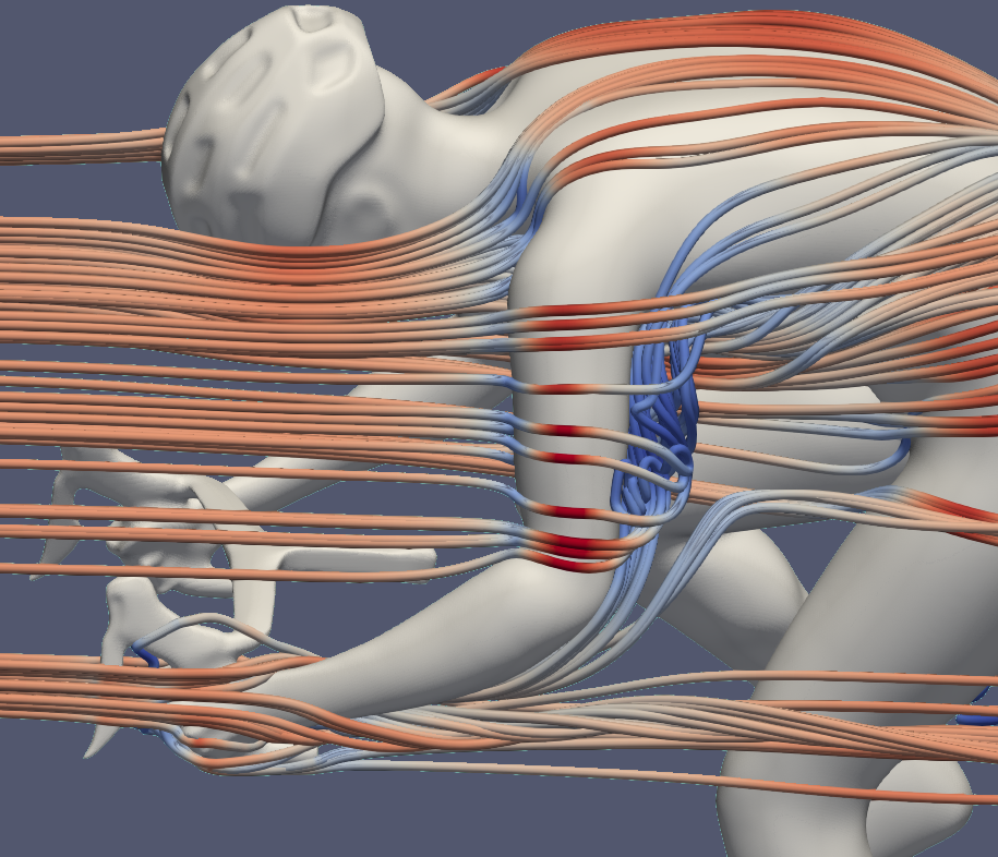
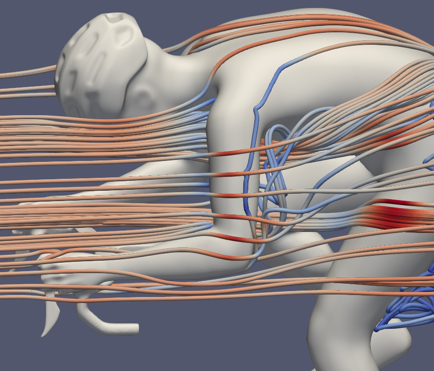
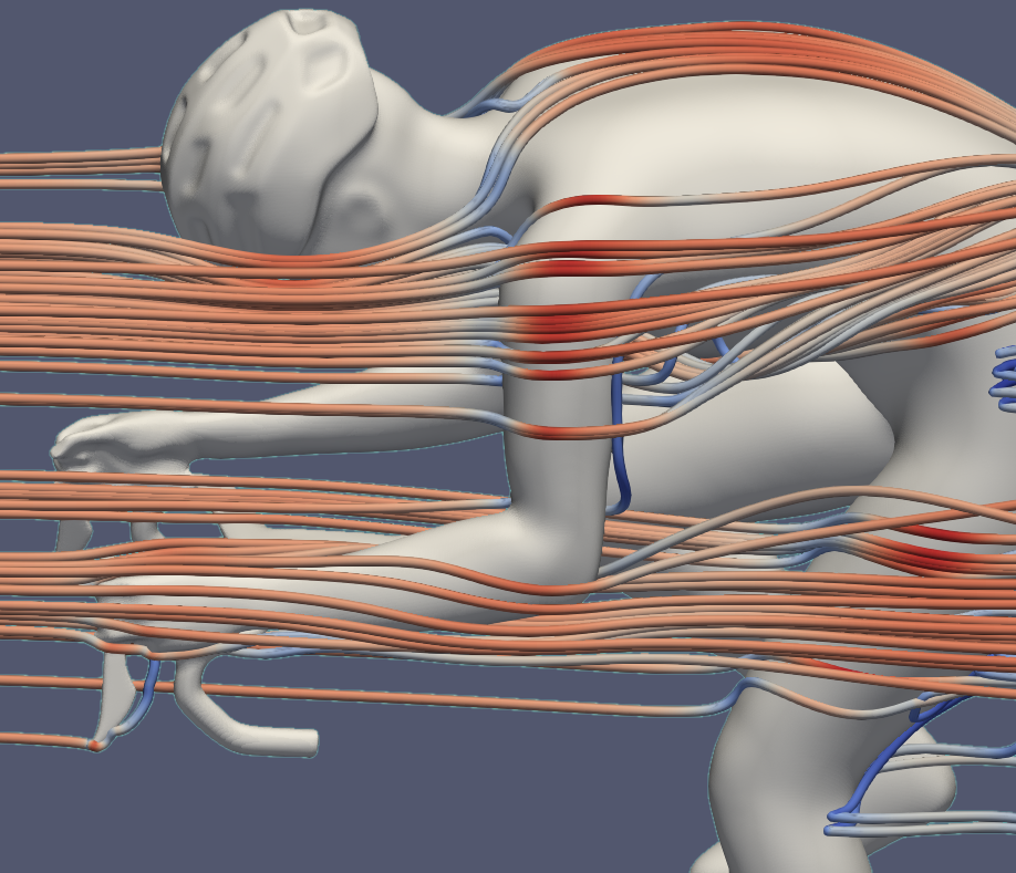
A qualitative analysis of the CFD simulation results illustrates the aerodynamic differences between the three riding positions. The streamlines (Fig. 2) reveal the following key behaviors:
• In the drops position, the flow generates a longitudinal vortex downstream of the hand, which separates from the surface at the wrist. Conversely, the flow over the forearms in both the hoods and hoods tucked positions remains smoother and more attached, showing no significant turbulence generation.
• On the downstream side of the upper arm air flows upward, creating a recirculating zone. This recirculation is most pronounced in the drops position and progressively diminishes in the hoods and hoods tucked positions.
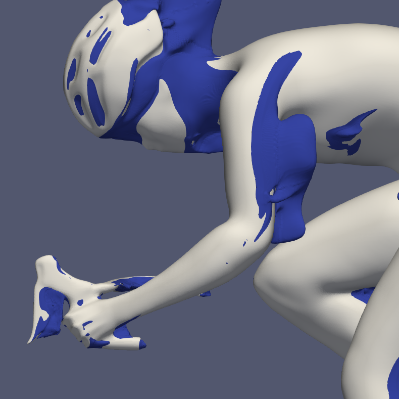
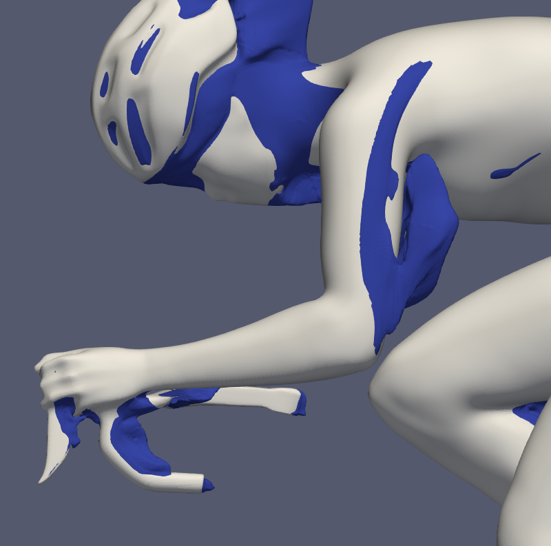
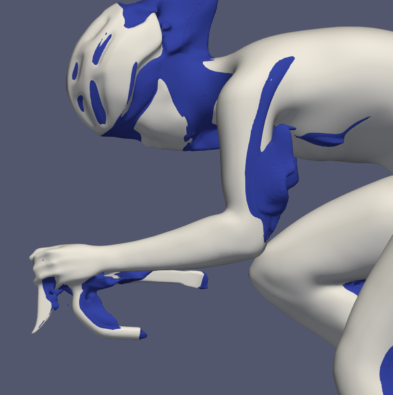
To visualize regions of reversed flow, a 3D iso-surface of streamwise velocity u = −0.1 m/s was extracted (Fig. 3), excluding areas of pure stagnation (u = 0). Prominent regions of velocity inversion appear behind the upper arm, with a more extended region in the drops position. By contrast, the hoods tucked posture exhibits the smallest area of reversed flow.
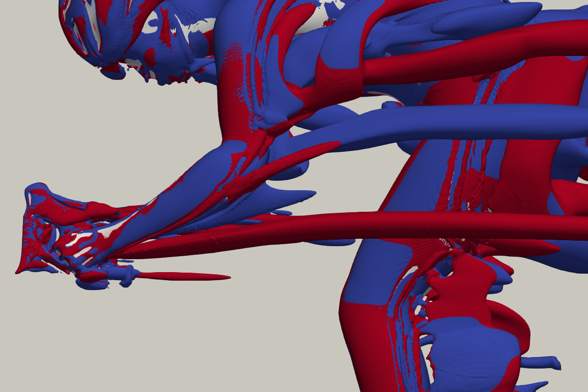
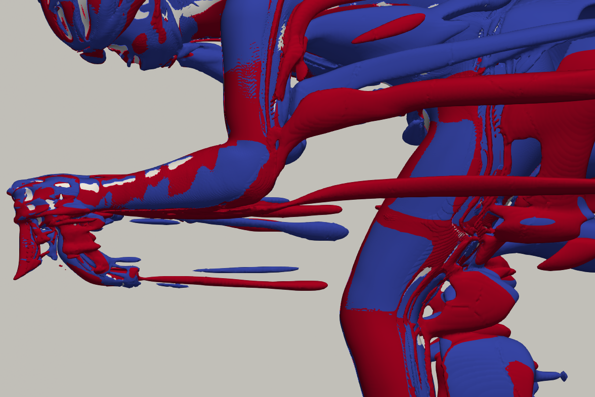
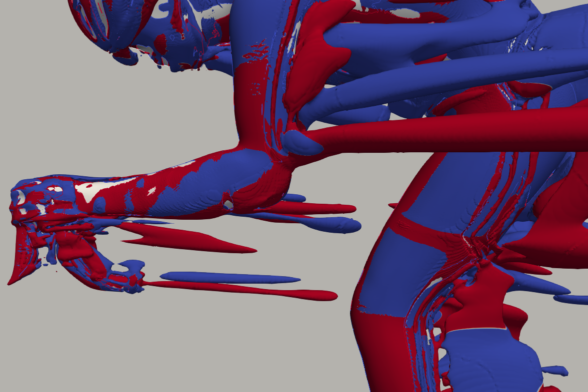
The close-up Q-criterion plots, where counterclockwise and clockwise vortices are shown in blue and red, respectively (Fig. 4), support these observations and provide further detail on vortex formation along the arms. In the drops position, a longitudinally extended vortex develops downstream of the wrist. Near the elbow, the flow separates from the surface, generating a pair of counterrotating vortices. These structures gradually diminish in intensity when moving from the drops to the hoods position and are weakest in the hoods tucked posture.
In the proximal upper arm, the vortical structures assume a more complex three-dimensional configuration and tend to merge with the torso turbulence.
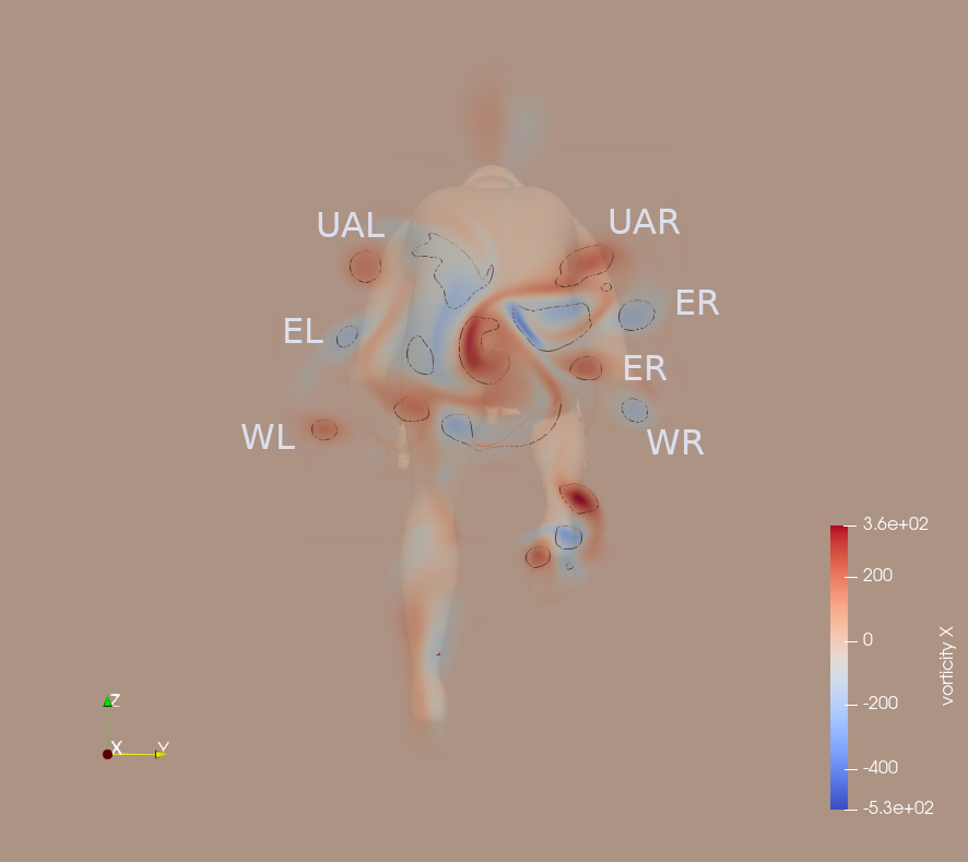
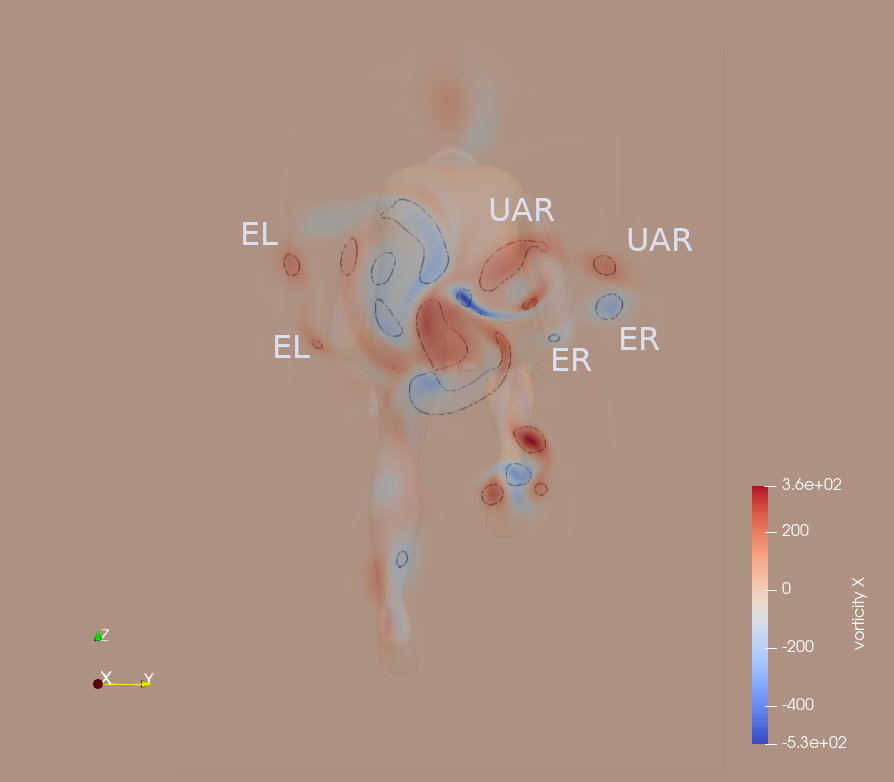
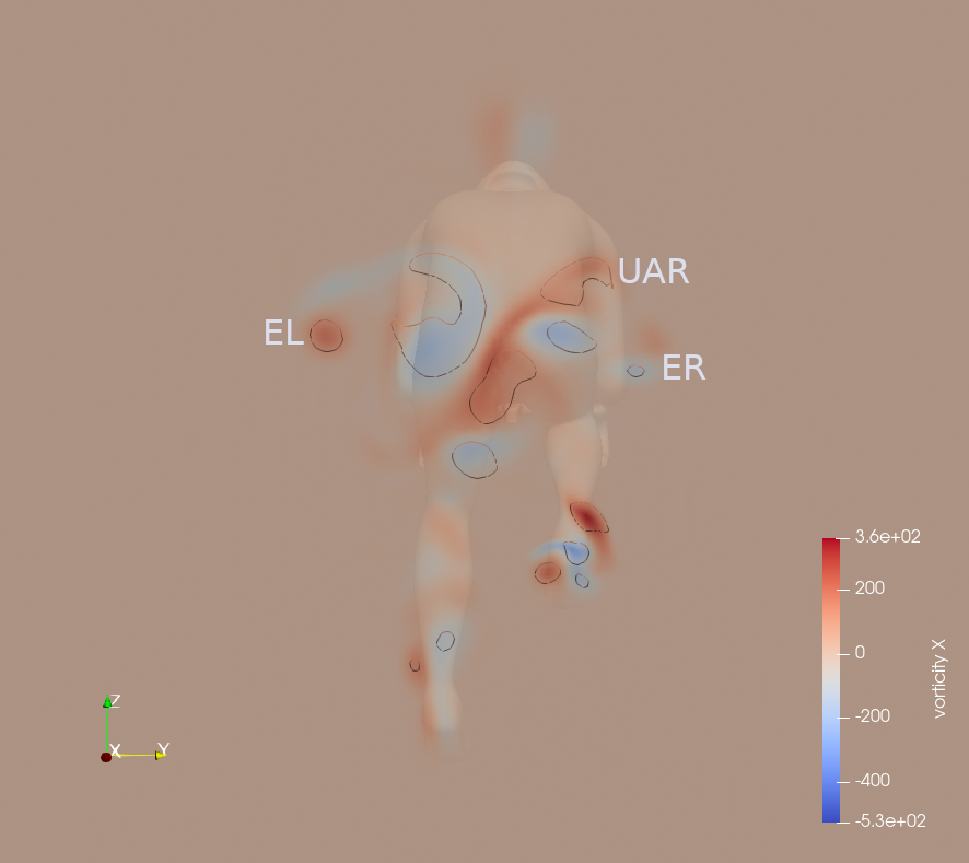
The near-wake section, taken 15 cm downstream of the cyclist, reveals the major vortical structures associated with the upper limbs. In the annotated plots (Fig. 5), arm-induced vortices are labeled as WR and WL (right and left wrist), ER and EL (right and left elbow), and UAR and UAL (right and left upper arm).
The influence of the arms on the wake diminishes progressively from the drops to the hoods position, and is the least pronounced in the tucked hoods configuration. Wrist vortices are only observed in the drops position, reflecting localized separation phenomena associated with the orientation and aerodynamic prominence of the forearms. Elbow vortices appear smaller in the hoods position and are either significantly reduced or no longer visible in the tucked position, as they dissipate earlier in the wake due to reduced protrusion. Upper arm vortices are partially visible in the first two positions but tend to merge with the flow structures generated by the lower torso on the right side when the arms are drawn closer to the trunk.
This progressive reduction and integration of arm-induced vortices reflect the aerodynamic streamlining achieved by narrowing the arm posture, especially in the final configuration.
Across all simulations, the total drag force was composed of approximately 95.6% pressure drag and 4.4% viscous (skin friction) drag. The key aerodynamic values for each position are summarized below.
| Position | Drag Force | % Change Drag Force (from Drops) |
Frontal Area (A) |
% Change FrontalArea (from Drops) |
Drag Coefficient (Cd) |
% Change Drag Coefficient (from Drops) |
| 1. Drops | 23.32 N | - | 0.388 m² | - | 0.501 | - |
| 2. Hoods | 22.39 N | -4.0% | 0.376 m² | -3.1% | 0.496 | -1.0% |
| 3. Hoods Tucked | 21.78 N | -6.6% | 0.369 m² | -4.9% | 0.492 | -2.0% |
Overall, the results demonstrate that posture adjustments can yield measurable aerodynamic benefits. The net drag reduction is a combined effect of geometric minimization of frontal area and incremental improvements in flow behavior, confirming that posture optimization plays a decisive role in road cycling aerodynamics.
Crouch, T. N., Burton, D., Brown, N. A. T., Thompson, M. C., & Sheridan, J. (2014). Flow topology in the wake of a cyclist and its effect on aerodynamic drag. Journal of Fluid Mechanics, 748, 5–35.